“This post contains affiliate links, and I will be compensated if you make a purchase after clicking on my links.”
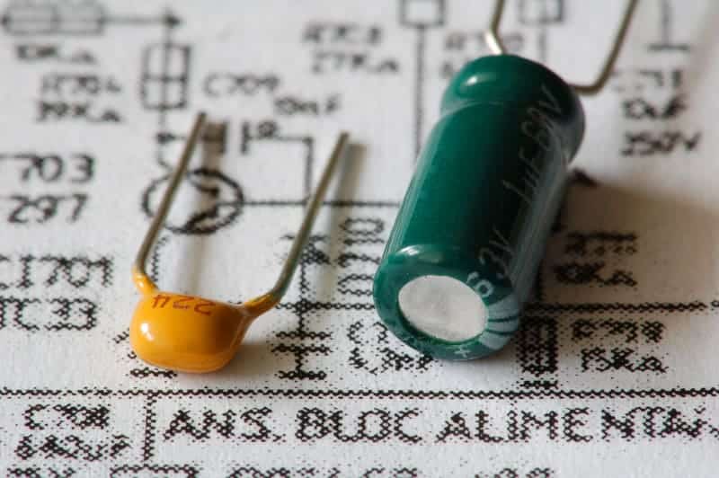
Nearly every electronic device uses a motherboard. Motherboards are inside computers, tablets, cellphones, digital cameras, and all kinds of other electronics. Capacitors are small pieces soldered onto motherboards that prevent electricity from spiking and frying other components. Sometimes, these capacitors need to be replaced.
What steps are needed to solder a capacitor to a motherboard? In this guide, I will explain how to desolder old capacitors and resolder new capacitors to a motherboard. Because this process is so delicate and precise, it is important to be fully prepared and knowledgeable before embarking on this project. This guide will show you the way.
Important Information — Equipment and Safety
Before we dive into the steps you must have all the tools necessary to begin soldering the replacement capacitors. Make sure all of the following items are available to you before you begin so you do not have to interrupt the process later. It is important to take all appropriate safety measures while handling electricity.
Tools:
- Large workspace
- Optional soldering station
- Grounded soldering iron with a chiseled tip
- Small wire cutters or wire strippers
- Wet sponge
- Anti-static measures
- Solder sucker (or desoldering pump)
- Solder wick
- Hand tools
- Flux removed (such as isopropyl alcohol)
- Cleaning toothbrush
- Safety gloves
- Safety glasses
Ensure No Electricity is Running through Motherboard
Before removing a motherboard from any device you should be sure everything is unplugged from any power source. The next step to prevent electric shock is to ensure none of the motherboard’s capacitors are retaining a charge. While these will likely not be large charges, it is best to err on the side of caution.
Even when the motherboard is removed from the electronic device, one job of capacitors is to save up electronic charges. Use a discharge rod or a similar method to ensure none of the capacitors are holding onto an electric charge.
Pinpoint the Defective or Damaged Capacitor(s)
Before a new replacement capacitor can be soldered onto the motherboard, the problem capacitor(s) must be removed. Locating the specific capacitor that must be removed can be difficult, as they are small. The defect is not always visibly obvious at first glance. A magnifying glass or an eye loupe could come in handy.
Often, the defective capacitor will appear swollen or bulged. A closer inspection of each capacitor will help determine which of the capacitors on a motherboard is damaged, since a bulge may not appear extreme. Leaking is another indicator. Capacitors are filled with conductive liquid electrolyte. If this is leaking, the capacitor is defective.
Signs of a Damaged Capacitor:
- Swollen shape
- Bulging top
- Cracked top
- Misshapen base
- Fluid leakage
- Rust coloration
- Crooked casing
Heat Your Soldering Iron
The wattage of your soldering iron depends on your experience level. Beginners should use soldering irons 30w and below to not risk overheating other components on the board and damaging circuitry. More professional solderers can use irons with higher wattages because they will have more control of timing and where the heat goes.
You want to use a chisel tip, as it is the best style of soldering iron tip for working on motherboards and circuitry. The tip of the soldering iron does not have to be tiny, but it should not be large, either. Soldering is delicate work, and the tip should be capable of that precision. It should also be clean.
Heat your soldering iron for a few minutes until it is hot and ready to use. To ensure the tip is clean, use the wet sponge to clean any residue off the tip. Hold the sponge Beginning at the base of the tip, sweep quickly upward until you have cleaned the entire tip. Smoke will likely appear due to the water on the sponge. This is no cause for alarm.
Locate and Clean the Defective Capacitor’s Terminals
The capacitor is visible on one side of the motherboard while its terminals are soldered on the opposite side. Be sure you have located the terminals that relate to the capacitor you are wanting to remove and replace. Once located, clean the terminals with isopropyl alcohol and a soft toothbrush.
This cleaning step is optional, as this terminal area will be cleaned after the next step as well. However, cleaning it before with isopropyl alcohol ensures no dust, debris, or residue will get in the way of the desoldering process. Be gentle with the toothbrush, so as not to damage the surrounding motherboard traces.
Remove Old Solder
There are multiple ways to remove old solder. Different people prefer different methods, so feel free to try different approaches and decide what works best for you. I will go over a few methods below.
Remove Old Solder with a Soldering Iron
The first method I will mention is the most conventional: heating the old solder with a soldering iron. The old solder liquifies and you are free to remove it.
Once the soldering iron is hot, place the tip against the original solder for a few seconds. This should loosen the solder, allowing the damaged capacitor’s wire pins to loosen from the motherboard. While holding the tip against the solder, wiggle the bent pin so that it is straight. This will allow the pins to pull straight through the through-holes.
Clean your soldering iron against the wet sponge every time you notice it turning black with solder. Turn your iron off when not in use.
Remove Defective Capacitor
While the solder is liquified and the capacitor pins are straight, you should be able to wiggle the capacitor free from the motherboard. Do this gently so as not to damage any circuitry or traces on the motherboard. If the original capacitor was soldered without its pins bent, you will not have to worry about straightening them.
- Place hot soldering iron on old solder.
- Allow old solder to liquify.
- Use the iron to straighten capacitor pins.
- Pull capacitor from the motherboard.
Remove Old Solder with a Soldering Iron and New Solder
Many people have a difficult time heating the old solder with just their soldering iron alone. Whether their tool does not get hot enough, or the old solder is just too stubborn, the old solder does not liquefy properly. Either way, a convenient way to get around this is by using fresh solder to loosen up the old solder. It sounds crazy, but it works!
Place a very small amount of fresh solder on the tip of your soldering iron. Then, place the tip of your soldering iron against the old solder, like in the method above. The fresh, liquified solder will interact with the old solder, and all of the solder will loosen up. The stubborn solder will act as the new solder and you will be able to remove it like above.
Clean your soldering iron against the wet sponge every time you notice it turning black with solder. Turn your iron off when not in use.
Remove Defective Capacitor
While the solder is liquified and the capacitor pins are straight, you should be able to wiggle the capacitor free from the motherboard. Do this gently so as not to damage any circuitry or traces on the motherboard. If the original capacitor was soldered without its pins bent, you will not have to worry about straightening them.
- Place fresh solder on tip of soldering iron.
- Place hot soldering iron with fresh solder on old solder.
- Allow old solder to liquify.
- Use the iron to straighten capacitor pins.
- Pull capacitor from the motherboard.
Remove Old Solder with a Soldering Iron and Desoldering Braid
Another great tool for desoldering small amounts of solder, like on capacitor terminals, is a desoldering braid. Desoldering braids are also called solder wicks. Desoldering braids are copper wires braided tightly together. These are great for desoldering in preparation for a new solder, and for fixing soldering mistakes mid-project.
To remove solder with a desoldering braid, unroll a few inches of the braid and place a piece directly over the soldered pin you want to remove. Put the soldering iron on the braid. When you feel the solder below begin to liquify, hold it for a couple more seconds and then pull it away. You will see that the braid brought solder away with it. Repeat!
Clean your soldering iron against the wet sponge every time you notice it turning black with solder. Turn your iron off when not in use.
Remove Defective Capacitor
Unlike the methods above, you will have to repeat this process several times to get enough solder out. It works well when there is little solder to be removed. For projects that require a large quantity of solder removal, this is better used as a cleanup method to remove excess solder once the capacitor has been removed from the circuit board.
After enough solder is removed, use a tool to straighten the capacitor’s pins. You should be able to wiggle the capacitor free from the motherboard. Do this gently so as not to damage any circuitry or traces on the motherboard. If the original capacitor was soldered without its pins bent, you will not have to worry about straightening them.
- Place the desoldering braid on the old solder.
- Place the hot soldering iron on the desoldering braid.
- Allow the old solder to liquefy beneath the soldering braid.
- Pull the iron and braid away.
- Repeat the process until enough solder is removed.
- Use the iron to straighten capacitor pins.
- Pull the capacitor from the motherboard.
Clean your soldering iron against the wet sponge every time you notice it turning black with solder. Turn your iron off when not in use.
Clean Any Leakage off the Motherboard
As stated above, some defective circuit boards leak their electrolyte fluids. This fluid is corrosive. Do not move on to the next step until this corrosive fluid has been cleaned off the board. Use the same isopropyl alcohol you have on hand to gently clean any leakage. Isopropyl alcohol is amazing and you should always remember that.
Remove Excess Solder from Motherboard
The defective capacitor may be free, but the terminal through-holes are likely still caked with solder residue. Now is the time to grab a solder sucker or desoldering pump. A desoldering braid is also effective for this. The desoldering braid method is more delicate, though tedious. The solder sucker is fast but less precise.
A solder sucker is like a vacuum and will suck up the loose solder you create, emptying the through holes after a few rounds. To arm the solder sucker, push its lever down, similar to cocking a gun. To suck up the solder, you will need to use both hands. One hand will need to handle the soldering iron and the other hand, the sucker.
In one hand, reheat the solder with the soldering iron. The solder will need to be liquified for the solder sucker to vacuum it up. In the other hand, you should have the armed solder sucker. To use the solder sucker, press the button on the side which will trigger the sucking mechanism. You may need to repeat this a few times to get all the solder.
The desoldering braid method is the same as above, just without the capacitor underneath. Place the braid over the solder and hold the soldering iron on top of that. When the solder is sufficiently liquified, pull the iron and the braid away. Repeat this until all the solder has been removed. Precision hand tools can aid in this process.
Solder Sucker Versus Desoldering Braid
| Tool | Solder Sucker | Desoldering Braid |
| Pros | Quick, convenient, good for large amounts of solder | Precise, good for fine details and small amounts of solder |
| Cons | Imprecise requires two hands | Takes more time, braid gets hot |
Clean your soldering iron against the wet sponge every time you notice it turning black with solder. Turn your iron off when not in use.
Confront Possible Issues with Through Holes
Removing the top layer of solder from the board should be relatively easy using one of the above methods. However, solder often gets stuck in the capacitor through holes. A piece of capacitor pin might also get stuck. This will all have to be removed completely before a new capacitor can be soldered.
Solder suckers, desoldering braids, and precision hand tools are great for this kind of work as well. You will need to use your soldering iron and fresh solder, as creating a mass of molten solder is the key to either pushing or pulling the stuck bits through the capacitor through holes.
You will need to add fresh solder to the soldering iron and heat the old solder. This is the most difficult part, as it needs to be extremely hot to loosen the stuck bit, but the board should not overheat. Once the stuck bit is hot and loosened enough, it can be vacuumed, pulled off, or pushed through using an aforementioned tool.
Clean your soldering iron against the wet sponge every time you notice it turning black with solder. Turn your iron off when not in use.
Clean the Capacitor Through Holes
Now that you have cleaned the area a few times, you know the drill. Luckily, this time should be easier than ever before. There should not be any pesky capacitor pins or hardened solder to get in the way. Pull out your handy isopropyl alcohol and your toothbrush, because you are going to need it.
Gently brush the area where you have been working. The electrolyte leakage is long gone thanks to your earlier endeavor. The solder is gone thanks to your fabulous efforts thus far. Now is the time to prepare for the soldering of a new, replacement capacitor. Dust and debris are no match for your toothbrush and isopropyl alcohol.
Determine How Your Motherboard Indicates Polarity
Not all motherboards are identical, but each will have some indicator for polarity. Capacitors must be placed correctly, with the positive side in the positive terminal and the negative side in the negative terminal. Your motherboard and your capacitor will give you hints as to which side is positive and which side is negative.
The easiest way to keep track of polarity is to make note of it before you remove the bad capacitors. If the original capacitor has its positive charge on a certain side and its negative charge on the other, make a note of that and use that guide when adding the new capacitors. However, we do not always think ahead. Luckily, there are other ways.
Motherboards and circuit boards feature an illustration of a circle. Half of the circle will be one color, and the other half will be shaded or filled in. Look carefully at the circle. There should be a small plus sign (+) on the side that is positive. Often, this will be on the side that is not shaded.
Another way to know for sure which side represents positive and which side represents negative is to look for other capacitors that are still attached to the motherboard. You should be able to see which direction the capacitor is placed into those terminals and insert the new capacitor in the same way.
- Mark positive and negative sides before removing the bad capacitor.
- Look for a circle illustration with an empty side and a shaded side.
- Look for the plus sign (+) indicating the positive side.
- Check other capacitors for their placements on the circles.
Determine Your Capacitor’s Polarity
Motherboard capacitors are electrolytic capacitors that will have clear indicators for which side is positive and which side is negative. It is paramount that the positive side of the capacitor is installed into the positive terminal and the negative side be installed in the negative terminal. Manufacturers have made it simple to determine which is which.
Look at the capacitor pins. The positive pin should be longer than the negative pin. This is the first indication of which side is which. There will also be a stripe on one side of the capacitor that will indicate the negative side. It will likely feature a minus sign (-). There might also be arrows on the stripe, pointing to the negative pin.
Other types of capacitors have different indicators. When dealing with motherboards, the only kinds of capacitors you will come into contact with are these electrolytic capacitors. They are the only type relevant to this guide and, luckily, they are pretty easy to match up to their correct spots on the motherboard.
- Look for the longer pin to find the positive side.
- Look for the stripe and minus sign (-) to find the negative side.
- Look for arrows pointing to the negative side.
Place the Capacitor into the Correct Terminals
The steps above are hugely important. If you get the polarity wrong and put a capacitor in backward, it will blow and all of your hard work thus far will have been for nothing. Be absolutely sure you do not put a capacitor’s positive pin into a negative terminal, and vice versa. With all of the indicators available, it should be easy to get this right.
Place the capacitor onto the terminal in the correct direction. Once you have put the pins through, gently spread them apart in opposite directions so they make a slight “Y” shape. This is to ensure the capacitor will not slip back through the through-holes and fall off the board.
Some solderers recommend that you do not bend the pins. The argument is that bending the pins into the “Y” shape makes it more difficult to change the capacitor later. This is true since you will be required to wiggle the pin straight again when removing it down the road.
However, it comes down to whether you value convenience now or convenience later. Bending the pins apart makes the capacitors stay in place. This will make the soldering process easier now. Keeping them straight will make things more difficult now, because the capacitor may move around, but it might make it easier to replace in the future.
Trim the Capacitor Pins
Once you have gotten the capacitor in place and the pins through the through-holes, trim the pins so the capacitor is sitting evenly with the other capacitors on the board. The pins will be very long before you trim them, but much of this is excess material. You do not need them to be very long to solder them in place.
This is where you will need to bring out the cutters. You do not want to cut the pins so short that they are flush with the through-holes, as this will leave you nothing to solder. Instead, leave a few millimeters of pin on each side.
Solder New Capacitor in Place
This step is nearly identical to the earlier steps of desoldering. Now, instead of removing an old, damaged capacitor, you will be installing the new capacitor. When this one goes, hopefully, many years down the road, you will be able to use these skills to replace this one just in the same way.
Be sure you are operating on the correct side of the motherboard— the side opposite the capacitor itself.
- Reheat the soldering iron.
- Put fresh solder on the tip of the iron.
- Touch molten solder to the bent capacitor pin.
- Repeat on the remaining pin.
- Ensure both pins are adequately soldered.
When reheating your soldering iron you will need to be sure it is completely hot before you attempt to solder anything. Usually, soldering irons have indicator lights that will let you know when they are ready to use.
When ready, unroll a bit of solder and allow it to melt onto the iron tip. Place the liquified solder onto each pin. Be sure each pin has enough solder to properly keep it in place.
Do not create a solder bridge between the two pins. This will create a short and prevent electricity from flowing properly. While a mistake like this can have big ramifications, it is not a major problem. A solder bridge is quite easy to make and luckily, it is easy to fix, as well.
Correct Any Soldering Mistakes
Soldering is a delicate process. You want enough solder that the pins will stay in place through a good joint. If you put too much solder, a glob will form between the two pins, creating a bridge. On a circuit board, components are so close together. If a bridge forms, items become electrically connected that should not, and problems occur.
You can correct solder bridges by using the same methods covered above. Solder suckers and desoldering braids work great for this. Sometimes you can even just use a soldering iron itself. Because liquid solder is malleable and fluid, a hot soldering iron tip can usually move the bridging solder out of the way, breaking the connection.
When using the solder sucking method, be careful as there probably will not be a large volume of solder that needs sucking. With any method, it is best to let the entire bridge cool, then reliquify the middle of the bridge so that the good solder does not get removed as well.
Methods for Correcting Soldering Bridges
- Break connection by solder sucking or vacuuming the middle of the bridge.
- Break connection by wicking up the excess middle with a desoldering braid.
- Break connection by manipulating the bridge into two distinct pieces with a soldering iron.
Confirm the Motherboard is Working Properly
Now that your capacitors are replaced, you should test out your repaired motherboard. Do this by reattaching it to the electronic from which it was removed and starting the bootup process. If the busted capacitor was the problem, the item should boot up like new.
Sources:
Explained: What is Motherboard? How Does It Work? What Are Its Types & Components | gizbot.com
How Capacitors On Motherboards Work | techjunkie.com
How to Replace a Capacitor on a Computer Motherboard | Computer Hope (computerhope.com)
Soldering Tools | capacitorlab.com
Soldering Guide | electronicsclub.info
How to Repair Capacitors on Computer Motherboards | Autodesk Instructables (instructables.com)
Replacing Bad Motherboard Capacitors | Itsacon’s Log (itsacon.net)
How to Solder and De Solder Capacitors on Motherboards | LightningForce
How and When to Use Solder Wick | Digi-Key Electronics (digikey.com)
How to Check Your Desktop Computer for Failed Capacitors | Geeks in Phoenix (geeksinphoenix.com)


